Your first knife template

Go beyond picking a size. Shape a Gyuto, refine its choil, place a pin hole and add a grind reference, then save an editable design and prepare a true-scale print.

This is a worked example, not a manufacturing specification. Follow along on a desktop with a mouse or trackpad; you can read the guide and view every example on a phone.

Open the Gyuto 210 template in a new tab Get a ready-made PDF

1. Get oriented

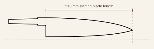
From Templates, choose Gyuto and Use 210 mm template, or use the link above. The starting profile is a 210 mm blade with a hidden tang.

Open Design settings at the right of the canvas. Essentials is at the top of that panel, above Blade, Tang & handle, Grind & steel and Details. If the panel is showing Selection, switch back to Design settings. Essentials is not shown on a blank drawing.

Use the mouse wheel to zoom and Pan to move around. Fit brings the drawing back into view. Keep Shape view while editing the outline; under View & snap → Canvas view, switch to the annotated view when you want dimensions and print marks.

Try changes freely: Undo reverses an edit.

Original Gyuto with a 210 mm blade and hidden tang
The starting profile.

2. Set the proportions

In Design settings → Essentials, enter these three values. Dimension lines on the drawing show blade length, tang length and heel height even in Shape view, and update as you reshape the template.

Blade length
200 mm
Blade height at heel
48 mm
Tang length
95 mm

You have changed three dimensions independently: the blade is shorter, the heel has its own height, and the tang has its own length. The handle does not have to shrink just because the blade does.

When to use Resize whole knife instead

Open Essentials → Resize whole knife, enter a target blade length in to length mm, then press Rescale. This scales the profile, tang, holes and other template dimensions together. Use it when you like the proportions and want a larger or smaller version. For this walkthrough, keep the three independent values above.

Gyuto resized to a 200 mm blade, 48 mm heel height and 95 mm tang
Proportions should usually be set first: blade length, blade height and tang length.

3. Shape the blade, not just its size

Open Blade → Tip and set Tip rise above edge datum to 32 mm. This sets the height of the point relative to the heel edge.

Then open Blade → Exact curve controls. Set Edge handle 2 height to 0.16 ×H. The curve lifts more through the forward portion of the blade while its endpoints stay fixed. Here, ×H means a fraction of the heel height, not millimetres.

For a more visual approach, choose Select and drag the curve handles on the canvas. Use the numeric controls when you want to reproduce a particular shape exactly.

Try a curve with more than one bend

Open More tools → Edit points, or press N while the canvas has focus. Click a curve to add a node, then shape the runs on either side. In Edit points, clicking a node cycles its corner, smooth and symmetric modes; Alt-click removes it. This is how you can build a flatter heel run followed by belly, rather than stretching one curve to do everything. Undo the experiment to return to the worked example.

Blade before adjusting the tip rise and forward edge handle
Before: the resized starting curves.
Blade after setting tip rise to 32 mm and edge handle 2 height to 0.16
After: a different point height and forward edge curve, with the same 200 mm blade length.

4. Refine the blade-to-handle junction

Open Tang & handle → Tang dimensions → Shoulders, curves & choil. Under Choil shape, choose Rounded finger relief. The choil wall stands straight up out of the ago and sweeps into the underside of the tang, scaled from this design’s own tang height.

Look closely at the sweep into the tang and compare it with the straight rise you started with. The heel corner itself is left square. This is a starting shape you can refine by dragging the choil handles on the canvas, not a locked profile.

The shoulder insets, shoulder positions, tang height and butt height are independent controls. Change them to suit your intended handle construction; a rounded choil alone does not establish fit or clearance.

Close view of the choil wall sweeping into the tang underside, with a square heel corner, on the worked Gyuto
A close-up of the worked choil: a straight wall curving into the underside of the tang, with the heel corner left square.

5. Add working details

Still in Tang & handle → Tang dimensions, find Pin holes and click + hole. For this example, set from ago to 45 mm, off centre to 0 and Ø to 3.2 mm. “From ago” measures back from the heel; zero offset centres the hole within the tang at that position.

Now open Grind & steel → Grind reference, enable Show bevel / shinogi line, and set Bevel height to 55%. This adds a reference line following the local blade height, rather than another cut edge.

Leave Show plunge line off, as it is on every starting profile: the bevel reference then runs the full length of the edge, which is what the example shows. Turn it on only when your grind starts forward of the heel, and set Plunge from ago to where it begins.

Switch to the annotated canvas view to inspect the reference marks. The print preview is the final check for what will appear on paper.

The hole and bevel values demonstrate the controls. Hidden tangs do not always need pins. Choose dimensions and hole placement for your own construction, and check that holes stay fully inside the tang.

Edited Gyuto with a 3.2 mm tang pin hole and a bevel reference at 55 percent of local blade height running the full edge with no plunge line
The worked profile now includes a pin location and a grind reference that runs the whole edge. These are different kinds of information from the outline itself.

6. Check it and save it

Choose Measure and click two points to check the distance between them. Zoom in when checking the junction and hole placement. You can choose Keep on drawing to retain a measurement; this is optional and is not included in the example shown.

Name the design Workshop Gyuto 200 in the header. Choose Sign in and then Create account if you do not have one; accounts are free. Save then appears beside the design name, and your designs open from Account → Designs on any browser you sign in to. That is the simplest way to come back later and change dimensions and curves.

Nothing is saved automatically. This browser keeps a local draft while you work, so a reload does not lose the design, and it is offered back to you the next time you arrive.

If you would rather not sign up, nothing here is closed to you: File → Download editable design .json writes the full editable model to a file, and File → Open editable design .json opens it again. It is also worth keeping a JSON copy of a saved design before you cut a major variant from it.

7. Prepare a true-scale print

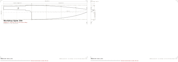
Open Preview & print. Choose A4 and Auto orientation. Check the actual sheet arrangement, including the hole, bevel reference and joins.

Open Print annotations to choose the printed grid, datum lines, dimensions and stock outline. These settings update the sheets immediately; they do not switch on extra clutter in Shape view. Mirror options are here too. The construction grid in View & snap is a separate, screen-only aid.

Under Advanced print settings, adjust safe margins if your printer clips the edges. Choose Trim and butt together for edge-to-edge assembly, or Overlap and glue when you want duplicated artwork at the joins. Keep Squeeze onto one sheet (NOT 1:1) off for a cutting template: it changes the scale.

Download the PDF, then print at Actual size / 100%. Measure the calibration ruler on paper: it must be exactly 100 mm. Check alignment at the join marks before assembling the sheets.

Read the full printing and calibration guide

Actual A4 sheet arrangement for the completed Workshop Gyuto 200 with pin hole and bevel reference
The finished worked example, tiled by the same layout engine as the app. This on-screen illustration is not a full-size printing file.

There is more than one way to build a knife here

The walkthrough stays with one parametric template. These are useful next steps when your design needs more than the example.

Plan thickness and distal taper

In Grind & steel → Steel & distal taper, enter the bar stock thickness. Under Distal taper, choose Add a profile and set thickness at stations along the blade. Enable Print the plan view (distal taper) to include the spine view at actual size.

Vary the bevel along the blade

Under Grind reference → Bevel height profile, use Add a profile to set heights at separate stations instead of one percentage. This lets you draw a rising or falling grind boundary. These are planning references, not a simulation of the finished grind.

Break out of the template

Save the design, or download a JSON copy, then choose Details → Edit as free drawing. The outline becomes an editable node path for shapes the template parameters cannot express. The blade, tang and grind parameters stop driving it; Undo reverses the conversion.

Draw from scratch

Choose Open blank drawing on the Templates screen. Build with Line, Curve and Hole, then use More tools for editing points, rounding corners, trimming and construction geometry. Close outline joins a path’s ends; Finish line leaves it open.

Arrange blanks on your stock

Stock nesting is a separate workspace for arranging profiles on a sheet or bar. Set stock dimensions and spacing, add the profiles you need, and inspect the resulting arrangement before exporting.

Explore the stock nesting workflow

Choose the right output

Use PDF for tiled printing, drawing SVG for the annotated drawing, cut line SVG for the clean outline, and DXF for compatible CAD or cutting software. Confirm units, geometry and machine requirements in the receiving application.

Back to the beginning · Browse all starting profiles